
Phase Converters
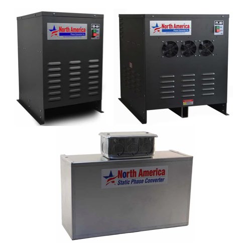
Essential devices known as phase converters are used to change single phase power into three phase power. They permit the operation of three phase equipment in locations where utility power is only available in single phase form. Many industries depend upon phase converters to run three phase motors and motor loads from a single phase electrical supply.
Rotary phase converters have garnered a wide respect for their durability and ability to handle many different load types, including resistive, inductive, and motor loads. These converters almost always include a control panel that manages the start-up process and regulates voltage output across all three legs of power. Because rotary phase converters deliver well-balanced three phase power, they are particularly good for running delicate three phase equipment in industrial and workshop environments. Proper voltage balance is crucial for the health and performance of three phase motors, and it also reduces stress on the connected equipment. In that area, rotary converters excel.
More Information about Phase Converters
More advanced applications have seen digital phase converters emerge as a reliable solution for generating clean, precise three-phase power. These units are under digital control and dynamically adjust output voltage to ensure stable performance across a spectrum of varying loads. Digital phase converters particularly shine when powering CNC machines and equipment that demand tight voltage regulation.
FAQs
Does the output voltage in phase conversion result in a third sine wave when dealing with multiple loads?
Yes, in phase conversion—particularly with rotary or digital phase converters—the output voltage includes a generated third sine wave to create balanced three phase power suitable for multiple loads.
How to Use a Multimeter
Measuring AC Voltage
Set the dial to the AC voltage symbol and plug the red probe into the voltage port. Place the red probe into the hot terminal block and the black probe into the neutral terminal block. Make sure the probes are fully seated to something that can conduct electricity, like the screws on the terminal blocks. The measurement is taken in parallel with the load.
Measuring DC Voltage
Set the dial to the DC voltage symbol and leave the probe in the same port as it was for the AC voltage measurement. Place the red probe to DC positive and the black probe to DC negative. The measurement is taken in parallel with the load.
Measuring Current or Amperage
Set the dial to either milliamps or amps. Move the red probe to the DC amp port. The multimeter is now set to measure DC current. Remove the wire that is sending power to the load and place one probe on one end and the other probe on the other, to complete the circuit, allowing power to bypass the load. The meter will break the circuit and measure the current in series with the voltage source. This allows the meter to measure the current that is going to the load.
Measuring resistance
Make sure that the load is disconnected from the electrical circuit, otherwise, the resistance measurement will not be accurate. Set the dial to the ohm symbol and place the red probe into the voltage port. Place one probe on one conductor and the other probe on the other. Take the reading.
Measuring Continuity
Meter settings stay the same as previous measurements, with the addition of pressing the audible button. Place the probes anywhere on the electrical circuit. An audible tone will sound if there is a continuous, point to point connection. If there is no sound, there is break in the electrical connection, possibly caused by broken or frayed wires.